Archives
lesson 3502
testtt
References
**To unlock access to the first quiz, make sure to select the “Mark as Completed” button below
References
- Sullivan R, Baston CM. When Not to Trust the Bladder Scanner. The Use of Point-of-Care Ultrasound to Estimate Urinary Bladder Volume. Ann Am Thorac Soc. 2019 Dec;16(12):1582–4.
- Taus PJ, Manivannan S, Dancel R. Bedside Assessment of the Kidneys and Bladder Using Point of Care Ultrasound. POCUS J. 2022 Feb 1;7(Kidney):94–104.
- Dessie A, Steele D, Liu AR, Amanullah S, Constantine E. Point-of-Care Ultrasound Assessment of Bladder Fullness for Female Patients Awaiting Radiology-Performed Transabdominal Pelvic Ultrasound in a Pediatric Emergency Department: A Randomized Controlled Trial. Annals of Emergency Medicine. 2018;72(5):571-580. doi:1016/j.annemergmed.2018.04.010
- O’Brian RA, Firan A, Sheridan MJ, Kou M, Place RC, Chung CH. Bladder Point-of-Care Ultrasound: A Time Saver in the Pediatric Emergency Department. The Journal of Emergency Medicine. 2021;61(3):e32-e39. doi:1016/j.jemermed.2021.04.010
- Ho-Gotshall S, Wilson C, Jacks E, Kashyap R. Handheld Ultrasound Bladder Volume Assessment Compared to Standard Technique. Cureus [Internet]. 2024 Jul 16 [cited 2025 Apr 10]; Available from: https://www.cureus.com/articles/180394-handheld-ultrasound-bladder-volume-assessment-compared-to-standard-technique
- Medical Advisory Secretariat. Portable bladder ultrasound: an evidence-based analysis. OntarioHealth TechnologyAssessmentSeries 2006; 6(11)
- Akca Caglar A, Tekeli A, Karacan CD, Tuygun N. Point-of-Care Ultrasound-Guided Versus Conventional Bladder Catheterization for Urine Sampling in Children Aged 0 to 24 Months. Pediatr Emerg Care. 2021 Aug;37(8):413–6.
- Chen L, Hsiao AL, Moore CL, Dziura JD, Santucci KA. Utility of Bedside Bladder Ultrasound Before Urethral Catheterization in Young Children. Pediatrics. 2005 Jan 1;115(1):108–11.
- Marzuillo P, Guarino S, Capalbo D, et al. Interrater reliability of bladder ultrasound measurements in children. Journal of Pediatric Urology. 2020;16(2):219.e1-219.e7. doi:10.1016/j.jpurol.2019.12.015
- Ma J, Mateer J. Ma and Mateer’s Emergency Ultrasound. 4e ed. USA: McGraw Hill; 2021
- Jade Deschamps, Vi Dinh. Bladder Ultrasound Made Easy: Step-By-Step Guide [Internet]. POCUS 101. Available from: https://www.pocus101.com/bladder-ultrasound-made-easy-step-by-step-guide/
- Lim LY, Chang SJ, Yang SSD. Age- and gender-specific normal post void residual urine volume in healthy adolescents. J Pediatr Urol. 2023 Aug;19(4):367.e1-367.e6.
- Chang S, Chiang I, Hsieh C, Lin C, Yang SS. Age‐ and gender‐specific nomograms for single and dual post‐void residual urine in healthy children. Neurourol Urodyn. 2013 Sep;32(7):1014–8.
- Chang SJ, Yang SSD. Variability, Related Factors and Normal Reference Value of Post-Void Residual Urine in Healthy Kindergarteners. J Urol. 2009;182(4S):1933-1938. doi:10.1016/j.juro.2009.02.086
Summary
Summary
> The bladder appearance and position vary depending on fullness
> The bladder is an anechoic structure. It should be evaluated in both the transverse and longitudinal orientation.
> Bladder volume calculation requires three unique measurements
>> Length – sagittal plane
>> Depth (height) – sagittal or transverse plane
>> Width – transverse plane
> PVR greater than 10% of the pre-void bladder volume estimated bladder capacity is generally considered abnormal
Pitfalls
Pitfalls & Challenges
- Inadequately distended bladders can be difficult to visualize
- The variety of bladder shapes leave volume measures as estimates rather than an absolute calculation
- Difficulty visualizing the Foley catheter: If the catheter is mispositioned, it can be challenging to visualize its proper placement via POCUS
- Bladder injury or rupture following trauma can be difficult to assess with PoCUS, as subtle injuries may not be easily detected, and the bladder may be challenging to visualize if there is significant free fluid accumulation or if the bladder shape is disrupted.
What is NOT Normal?
Elevated Post-Void Residual
Bladder capacity and PVR volumes increase with age and can vary by gender [12,13]. As such, no single cutoff defines an elevated PVR in all pediatric patients. However, a PVR greater than 10% of the pre-void bladder volume estimated bladder capacity is generally considered abnormal and warrants further investigation [14]. Clinical judgment remains essential, as acceptable PVR values may vary depending on the child’s age, gender, bladder capacity and individual clinical context. Always refer to your institution’s local guidelines for specific reference ranges.
Debris
Debris within the bladder lumen in non-catheterized patients is not considered normal and may indicate an underlying issue (figure 15). Additionally, dense debris (seen as echogenic masses or clumps within the bladder) in catheterized patients is also not considered normal and may suggest complications such as infection, bladder stone formation, or catheter-related obstruction.
Residual bladder fullness post catheterization
If the bladder remains distended after catheter drainage, it may indicate that the Foley catheter is either obstructed or mispositioned, preventing complete drainage (Figure 16).
*Residual fluid within the bladder would only be normal if the catheter has been intentionally clamped for bladder filling.
Foley balloon mispositioning
If the Foley catheter is not visualized within the bladder lumen, it may be mispositioned outside the bladder, in the urethra, or in adjacent structures, which could interfere with proper drainage and function (Figure 17).
Figure 15: Distended bladder in the transverse position with echogenic debris.
Figure 16: Distended bladder despite Foley catheter in situ, suggesting the catheter is clamped or obstructed. Video courtesy of Dr. Dave Kirschner, used with permission.
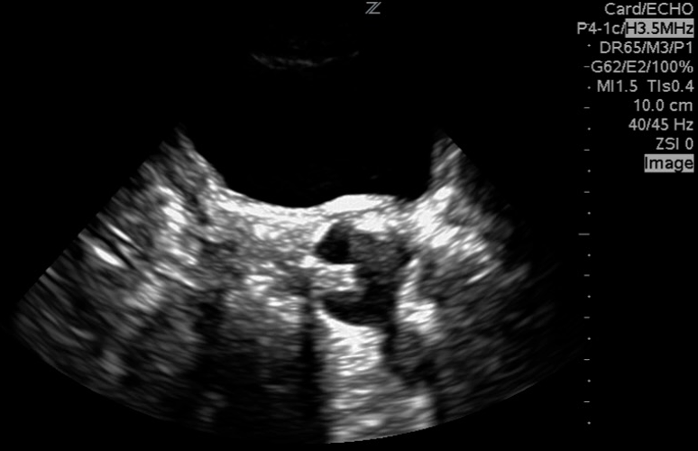
Figure 17: Sagittal image of the bladder with foley catheter in the urethra. Image courtesy of Dave Kirschner, used with permission.
What is Normal?
The shape and relationships of the bladder on ultrasound examination will depend on its degree of filling. The sagittal view is triangular (figure 10), and the transverse view is rectangular (figure 11). That said, the shape varies depending on bladder fullness. When distended, the bladder walls appear thinner compared to a thicker appearance when less distended (figure 12).
No single cutoff defines a normal bladder capacity or normal PVR across all pediatric patients due to variability with age and gender. However, as a general rule of thumb, a PVR less than 10% of the estimated bladder capacity is considered normal [12-14].
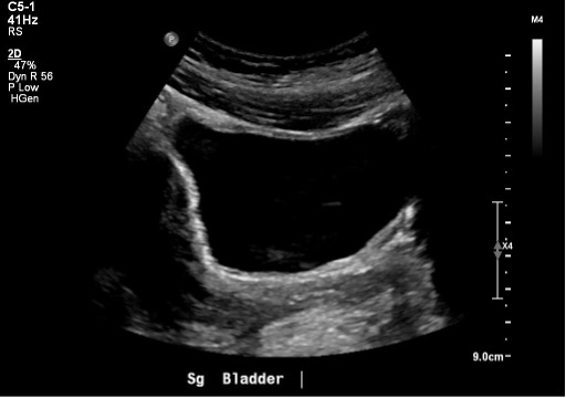 Figure 10: Normal bladder in the sagittal plane
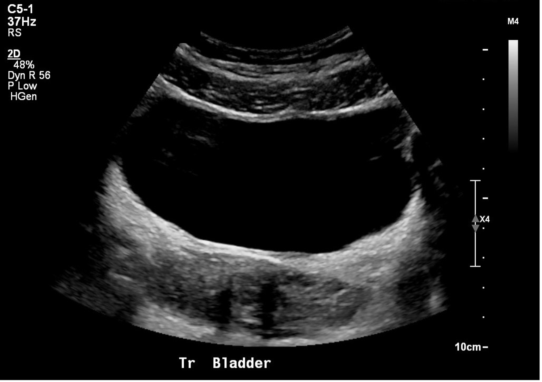
Figure 11: Normal bladder in the transverse plane
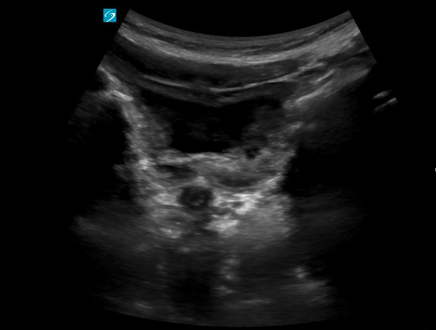 Figure 12: Transverse view of a near empty bladder with thicker walls
Catheterized Children
In catheterized children with a Foley in place, the bladder may appear partially or completely decompressed depending on recent drainage. The Foley catheter is typically visualized as a linear echogenic structure within the bladder lumen, often with posterior shadowing. The inflated balloon at the catheter tip appears as a well-defined, round anechoic or hypoechoic structure with an echogenic exterior rim, centrally located within the bladder (Figure 13).
Note: The presence of internal debris within the bladder lumen (seen as echogenic material or echoes within the fluid) may be considered a normal finding in patients with long-term catheter use.
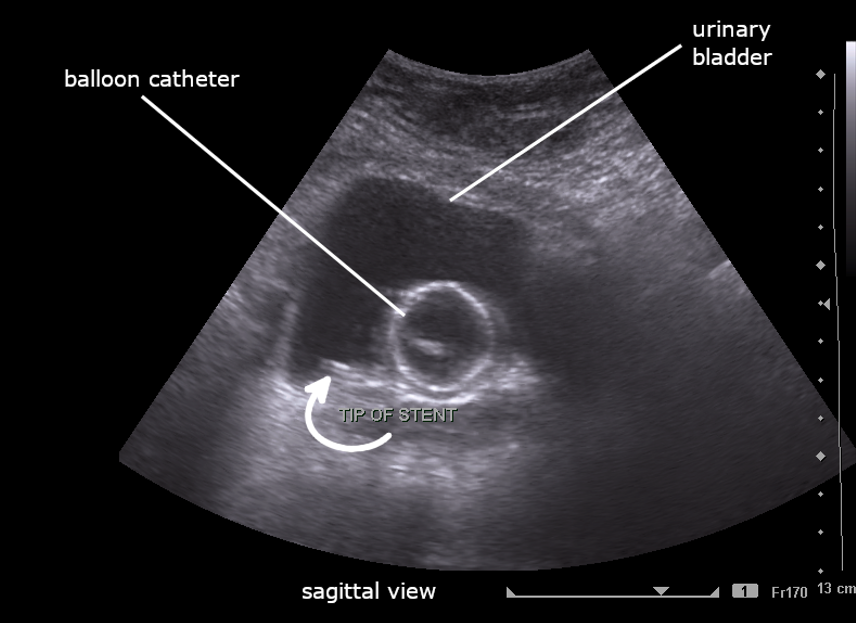
Figure 13: Sagittal image of partially filled bladder with Foley catheter. Image By Cerevisae – CC BY-SA 4.0 license.
Figure 14: Transverse view of a fully decompressed bladder with a normal foley balloon. Video courtesy of Dr. Dan Kim, used with permission.
What am I looking at?
Orientation
When scanning the bladder, like with any ultrasound, the transverse plane provides a cross-sectional view, with patient right on the screen’s left, patient left on the screen’s right, and anterior in the near field and posterior in the far field. In the sagittal plane, cranial is on the screen’s left, caudal is on the screen’s right, with anterior in the near field and posterior in the far field.
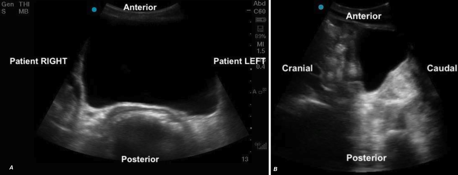 Figure 5ab: Transverse and sagittal bladder views with orientation labels
Appearance:
The bladder will appear as an anechoic cavity surrounded by echogenic walls.
Position
The bladder sits in the pelvis just posterior to the pubic symphysis. Its size and position relevant to other structures varies according to bladder fullness.
> Full Bladder:
– Sits anterior to the uterus in females (figure 7a, 9a)
– Sits cranial and anterior to the prostate in males (Figure 7b,9b)
– Anterior to the rectum
> Partially filled:
– Sits lower in the pelvis, appearing caudal to the uterus (figure 8)
– Remains anterior to the prostate in males but is positioned lower in the pelvis
– Anterior to the rectum (figure 8)
It’s important to be aware that in younger pediatric patients, when the bladder is near empty, surrounding structures such as the uterus or prostate may also be difficult to identify due to their size or degree of development.
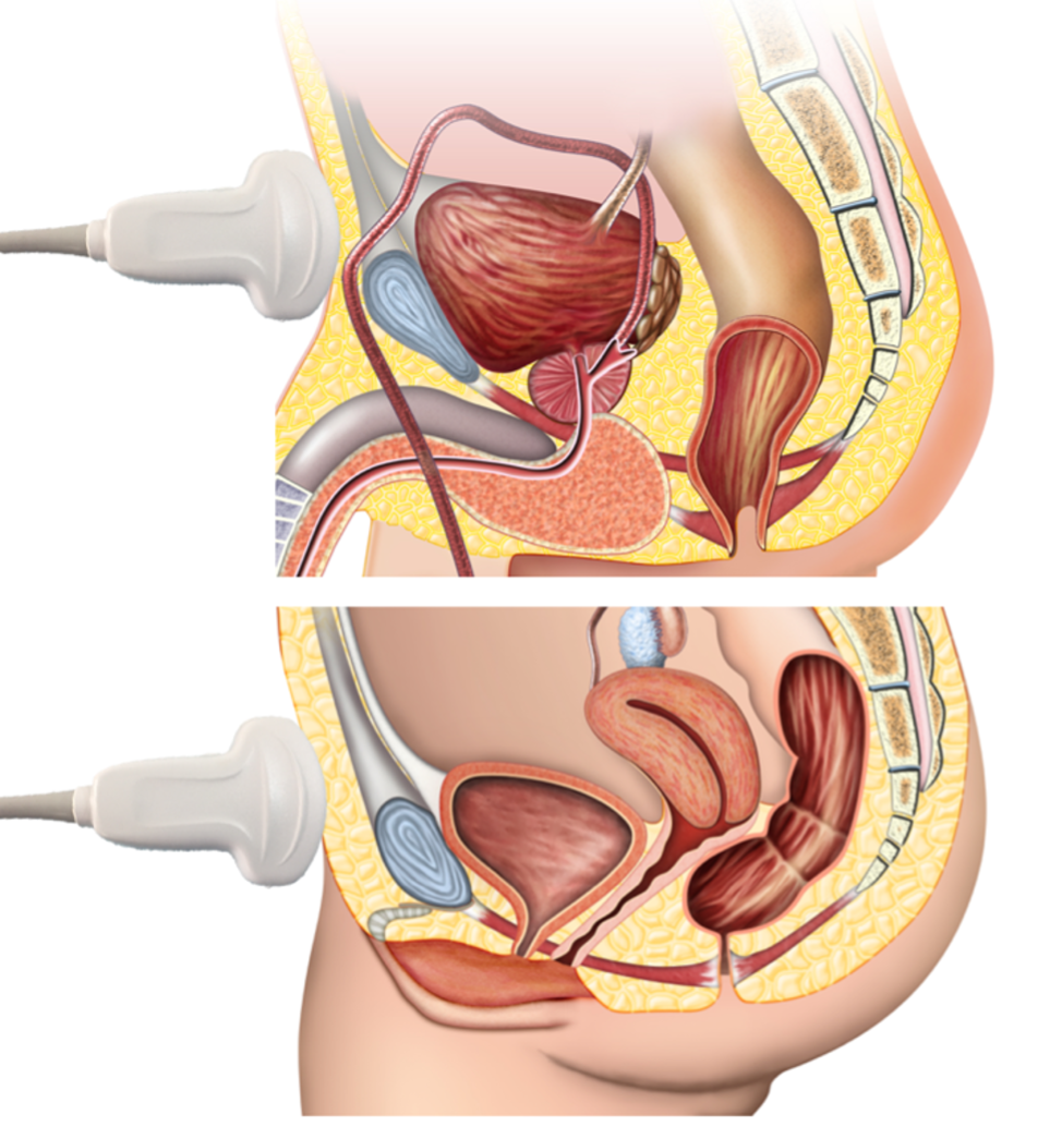
Figure 6: Anatomic diagram of pelvic structures illustrating key landmarks for bladder ultrasound scanning, including the bladder, uterus/prostate & rectum
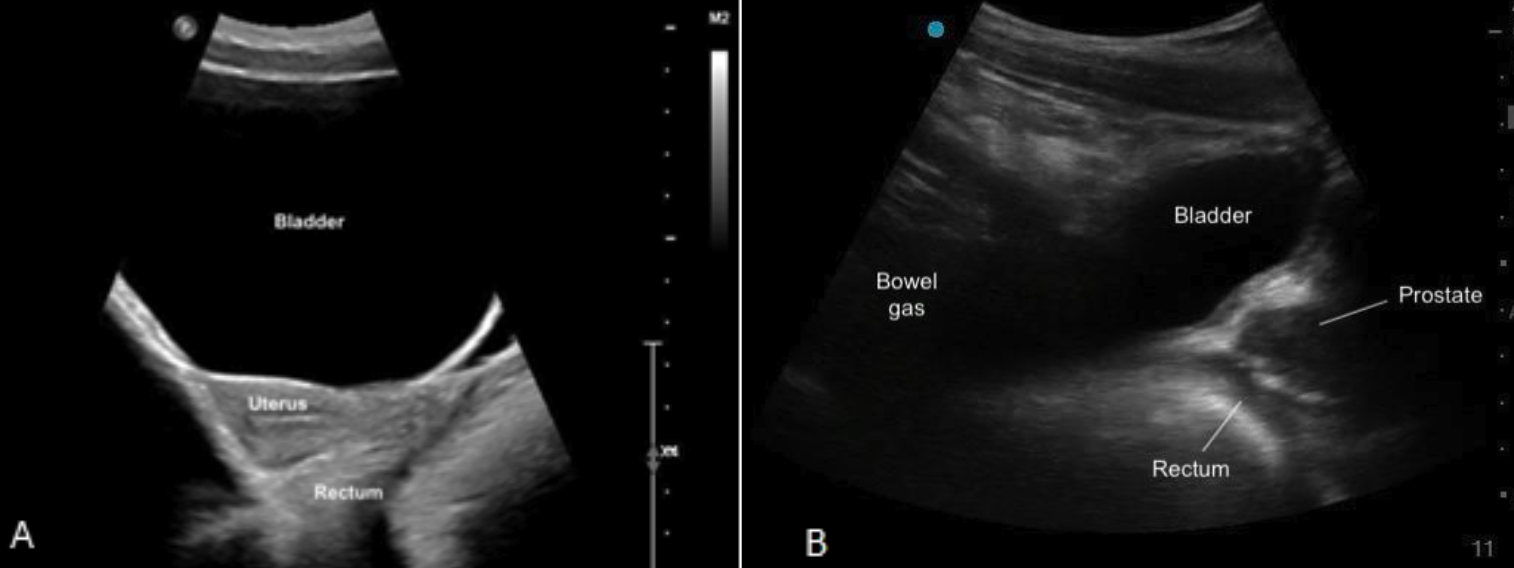
Figure 7ab: Sagittal bladder sonoanatomy in female (a) and male (b) children.
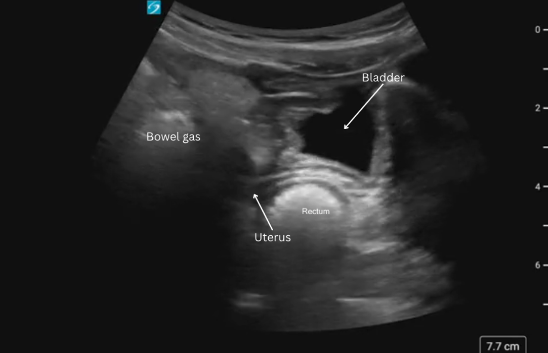
Figure 8: Sagittal view of bladder sonoanatomy in a female patient with a near empty bladder.
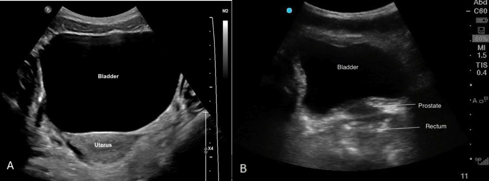
Figure 9ab: Transverse bladder scan sonoanatomy in female (a) and male (b) chidlren.
Technique
Bladder Scan Technique:
1. The patient will lie supine.
2. Identify the symphysis pubis (figure 1) and place the probe just superior on the lower abdomen with the probe indicator facing patient’s right
3. Identify the bladder

4. Scan thoroughly in the transverse plane by fanning the probe cranial to caudal
5. Rotate the probe 90 degrees clockwise to obtain a sagittal probe position (probe marker pointed cranially).
6. Scan thoroughly in the sagittal plane by fanning through the bladder from hip to hip.
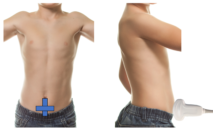
Figure 1. Bladder volume probe positioning
Bladder Volume Technique:
Bladder volume can be determined non-invasively by measuring the bladder in its maximal width, depth, and length. Bladder volume can be calculated both pre- and post-void.
1. Scan the bladder in two planes to obtain three unique measurements (Figure 2)
> Width: In the transverse plane, measure the diameter between the lateral walls to obtain the width.
> Depth (height): is the anteroposterior diameter, which can be obtained in the transverse or sagittal plane. Choose just one plane for this measurement.
> Length: is the craniocaudal diameter, which is obtained by measuring from the superior to inferior wall of the bladder in the sagittal plane.
2. Calculate Volume
> Most current machines contain automated calculators for volume measurement.
– To access the bladder volume calculation package, select the Calculations/Calc button on your ultrasound system. Then search for or navigate to the Bladder Volume option within the calculation menu. Once selected, choose the L, W, or H measurement – as appropriate for the imaging plane you are in.
> As an alternative, the simple formula (LX W X D X 0.7) can be used to estimate bladder volume.
– However, because of the inherent variability of bladder shape and the variation in this shape with differing degrees of filling, bladder volume measurements obtained in this fashion may have an error rate between 15% and 35% [10].
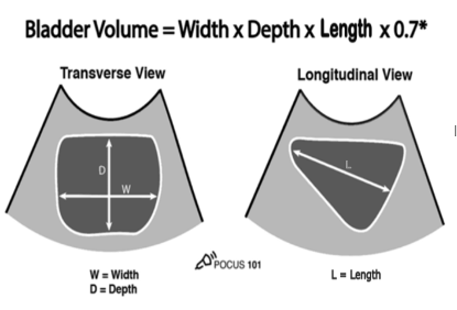
Figure 2: Measurements for bladder volume in transverse and sagittal planes [11]
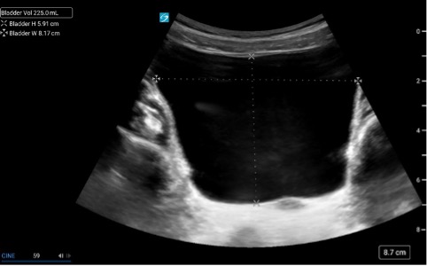 Figure 3.
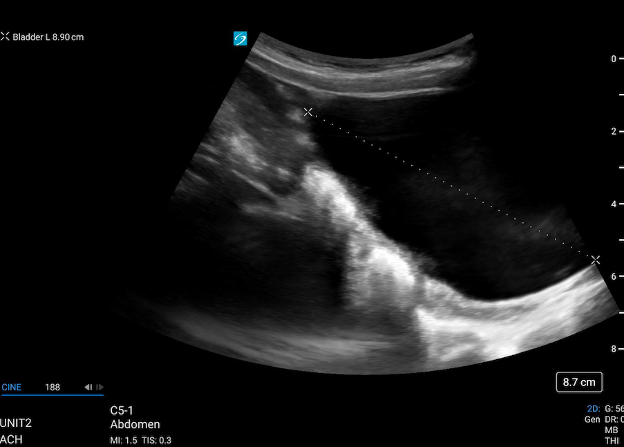 Figure 4.
Figure 3 & 4: Caliper placement for bladder volume in the transverse and sagittal planes.