**To unlock access to the first quiz, make sure to select the “Mark as Completed” button below
References
- Sargent MA, Babyn PS, Alton DJ. Plain abdominal radiography in suspected intussusception: a reassessment. Pediatr Radiol. 1994;24(1):17–20
- Tsou PY, Wang YH, Ma YK, et al. Accuracy of point-of-care ultrasound and radiology-performed ultrasound for intussusception: A systematic review and meta-analysis. Am J Emerg Med 2019 Sep;37(9):1760-9.
- Riera A, Hsiao AL, Langhan ML, et al. Diagnosis of intussusception by physician novice sonographers in the emergency department. Ann Emerg Med 2012;60(3):264-8.
- Arroyo AC, Zerzan J, Vazquez H, et al. Diagnostic Accuracy of Point-Of-Care Ultrasound for Intussusception Performed by Pediatric Emergency Medicine Physicians. J Emerg Med 2021 Jan 19:S0736-4679(20)31330-5.
- Kim JH, Lee JY, Kwon JH, et al. Point-of-Care Ultrasound Could Streamline the Emergency Department Workflow of Clinically Suspicious Nonspecific Intussusception. Pediatr Emerg Care 2020 Feb;36(2):e90-95.
- Sharma P, Al-Sani F, Saini S, et al. Point-of-Care Ultrasound in Pediatric Diagnostic Dilemmas: Two Atypical Presentations of Intussusception. Pediatr Emerg Care 2019 Jan;35(1):72-4.
- Doniger SJ, Salmon M, Lewiss RE. Point-of-Care Ultrasonography for the Rapid Diagnosis of Intussusception: A Case Series. Pediatr Emerg Care 2016 May;32(5):340-2.
Summary
- Intussusception should be considered in young children with abdominal pain, particularly when clinical signs are non-specific or vague.
- Ultrasound has excellent diagnostic accuracy for intussusception and POCUS was not significantly different from radiology-performed ultrasound. It is a good “rule in” test in the ED.
- The “Inverted U” technique provides a systematic approach to scanning the abdomen and increases the likelihood of identifying ileocolic intussusception.
- Always confirm abnormal findings in two planes, measure transverse diameter, and use color Doppler to assess perfusion.
- Key ultrasound findings of intussusception:
“Target” or “doughnut” sign (>2.5–3 cm in diameter for ileocolic) — Transverse view
“Pseudokidney” or “sandwich” appearance — Longitudinal view
- Normal bowel differentiation:
Small bowel: smaller calibre, fluid-filled, peristalsis present
Large bowel: larger calibre, gas/stool-filled, haustral folds, minimal peristalsis
- Early identification and expedited management of intussusception via POCUS can reduce ED length of stay and improve outcomes.
It is important to visualize an intussusception in both planes to reduce the likelihood of mistaking it for thickened bowel loops, psoas muscle, stool, or other abdominal masses (Figure 11).
Small bowel intussusceptions can often be seen in the abdomen and in most cases are transient and do not require treatmentgenerally less than 2cm in diameter) and for the presence of peristalsis (absent in ileocolic intussusceptions) (Video 4).
Pathologic lead points may not be easily recognized with POCUS, therefore consider other imaging modalities when patients are outside the typical age range or with suggestive history or physical examination findings.
Ileocolic intussusception may self-reduce, therefore a positive POCUS examination with a subsequent negative radiologist-performed ultrasound is possible.
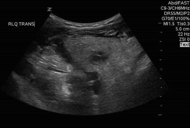
Figure 11: Inflamed, thickened bowel, not to be mistaken for intussusception
Video 4: Small bowel intussusception with the presence of peristalsis
What is NOT Normal?
Intussusception will appear differently due to the loss of air from the telescoped bowel. As a result, you are more easily able to visualize the intussusception compared to normal bowel. In the transverse view an intussusception appears as a “target” or “doughnut,” which is created by a hyperdense centre surrounded by multiple concentric hyperdense rings (Figure 6,8). This should have a minimum diameter of 2.5-3 cm with ileocolic intussusception. A “target” with a diameter of 2 cm or less suggests a small bowel intussusception, which generally self-resolve, and rarely require reduction. Intussusception appears as a “pseudokidney” or “sandwich” in the oblique or longitudinal view because of the multiple hypoechoic layers (Figure 10).
– The diameter of intussusceptions are typically estimated visually or “eye-balled.” However, if there is any uncertainty, callipers can be used to measure the anterior-posterior (AP) diameter from outer edge to outer edge in the transverse plane
In the case of a true ileocolic intussusception other findings can often be noted on ultrasound including small amounts of free fluid outside the intestine in the area of the intussusception as well as a small bowel obstruction. These findings are outside of the scope of this module and are discussed in the small bowel obstruction module.
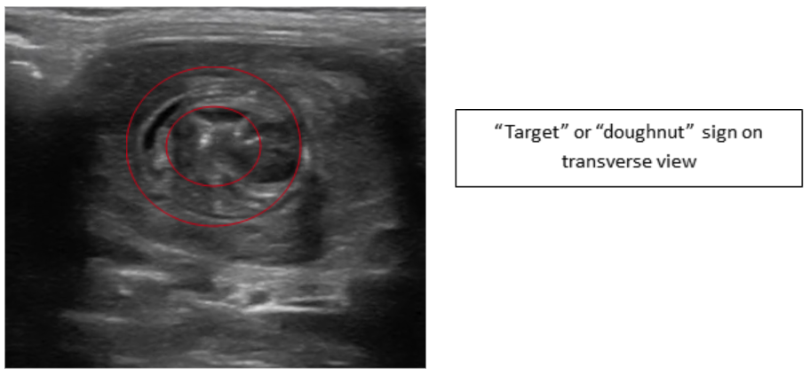 Figure 6: Transverse image intussusception—Target or Doughnut sign
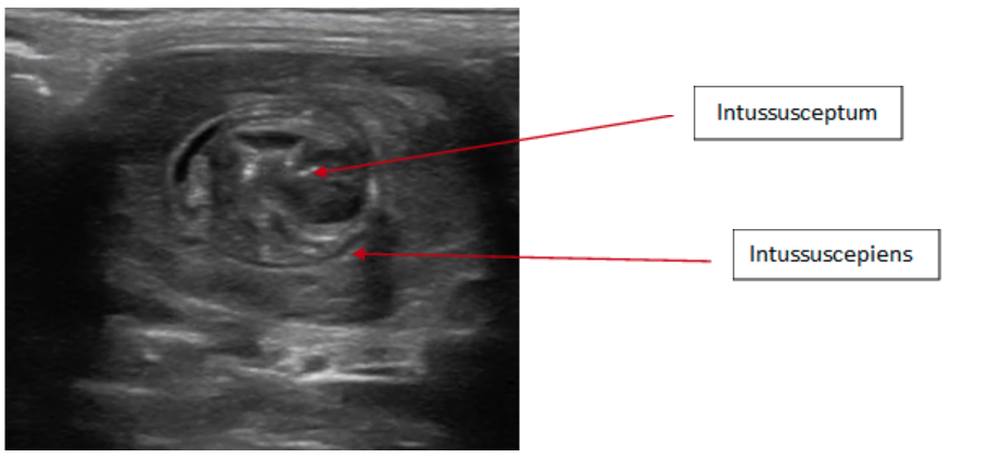 Figure 7: Transverse image intussusception, telescoping of the intussusceptum into the intussuscepiens
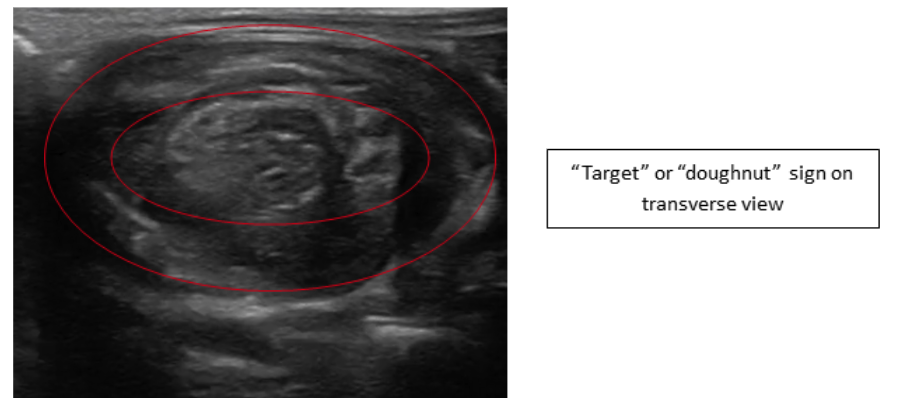 Figure 8: Transverse image intussusception—Target or Doughnut sign
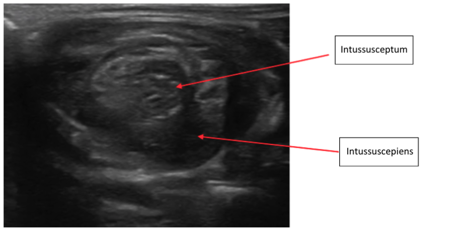 Figure 9: Transverse image intussusception, telescoping of the intussusceptum into the intussuscepiens
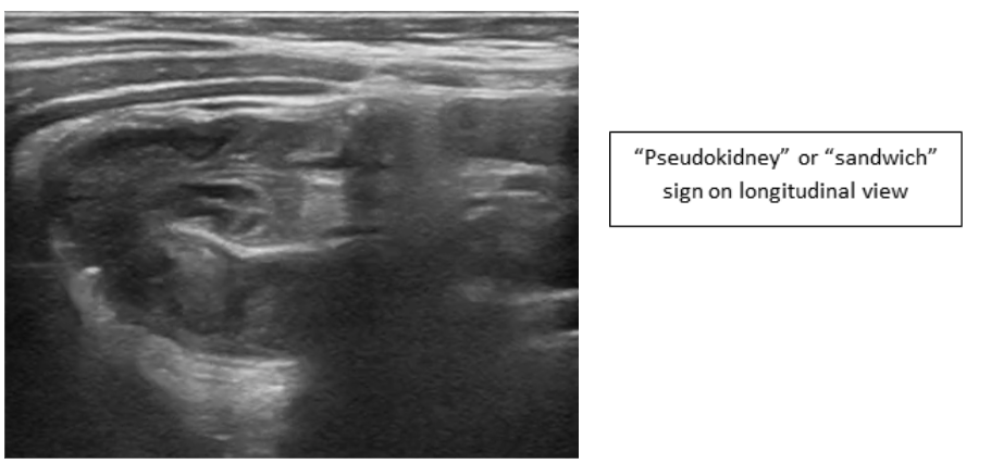 Figure 10: Intussusception “pseudokidney” or “sandwich” in the oblique or longitudinal view
Video 3: Normal bowel transitioning into Intussusception
What is normal?
First it is important to identify the cecum in the right lower quadrant as the beginning of the large bowel. To identify the cecum first place the probe in the RLQ and identify the psoas muscle and iliac vessels in cross section [Figure 4]. Lateral to the psoas muscle the cecum can be identified as a gas or stool filled structure 5].
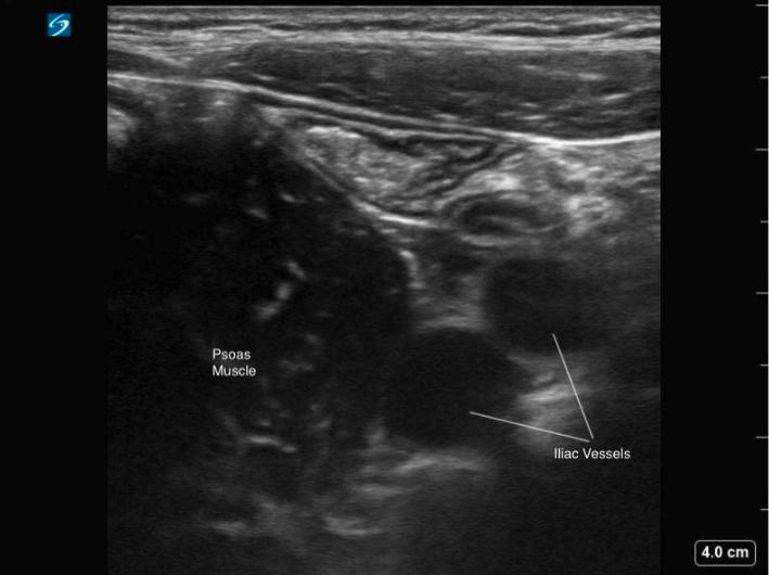 Figure 4: Transverse image of the RLQ, showing the iliac vessels in cross section and psoas muscle
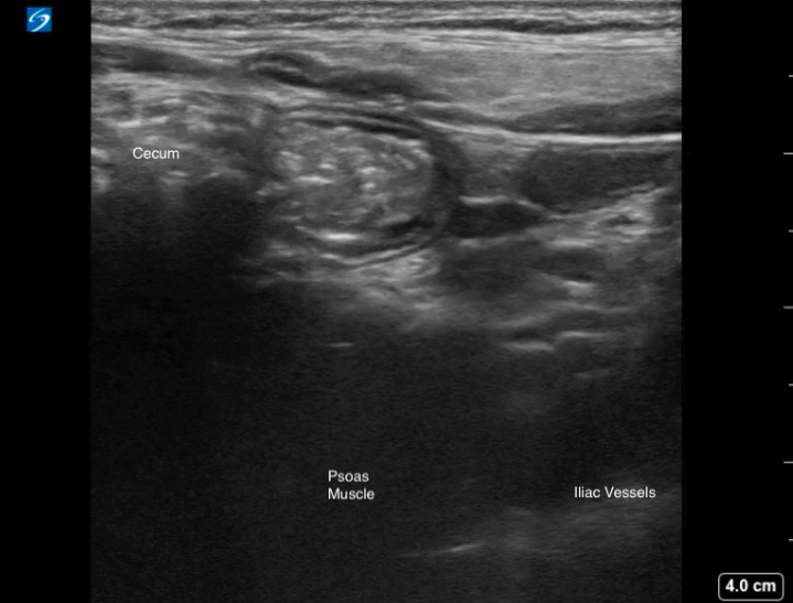
Figure 5: Transverse image of the RLQ demonstrating a gas-filled cecum with posterior shadowing, positioned lateral to the psoas muscle.
Video 1: Transverse scan through the RLQ, displaying the gas filled cecum laterally and normal appearance of the terminal ileum with a smaller luminal caliber.
On ultrasound, distinguishing between small and large bowel can sometimes be challengingTypically, small bowel appears as having a smaller luminal caliber, contains fluid contents within, and demonstrates active peristalsis. Whereas large bowel has a larger calibre, is typically filled with gas or air and stool, has haustral folds and lacks peristalsis (Video 2).
Video 2: Normal large bowel, displaying haustral folds and lack of peristalsis
Intussusception occurs when one part of the bowel telescopes into another part of the bowel [figure 2]. 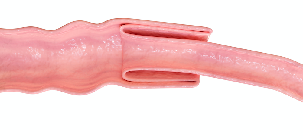
Figure 2: An intussusception occurs when one part of the bowel telescopes into another
While intussusception can happen at any location along the bowel, ileocolic intussusception is the most common type of intussusception occurring in children requiring timely intervention to resolve and the focus of this module. This occurs where the ileum and cecum connect [figure 3].

Figure 3: Ileocolic intussusception is the most common intussusception in children and is the focus of this module. It occurs when the terminal ileum of the small bowel telescopes into the colon.
To look for an ileocolic intussusception the exam begins in the right lower quadrant of the abdomen and follows the course of the large bowel.
Technique
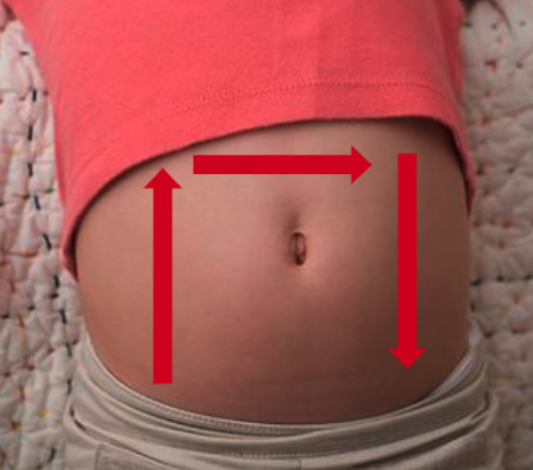
Figure 1: The inverted “U” technique to identify ileocolic intussusception
While several techniques have been described, we will focus on the one known as the “Inverted U” [figure 1]:
- With the patient supine and in a position of comfort (possibly in the parent’s lap) place probe in the right lower quadrant with the probe marker aimed to the patient’s right while in the transverse plane. The psoas muscle and iliac vessels can be identified as the starting landmark on the right of the screen.
- Move the probe laterally until the cecum is identified. From here you will follow the path of the large intestine to identify any evidence of intussusception.
- With the probe in the transverse plane, slowly move the probe superiorly to the right upper quadrant until the liver and gallbladder are visualized as landmarks—following the course of the large bowel.
- Rotate the probe 90 degrees clockwise so the probe marker is aimed toward the patient’s head and move the probe along the epigastrium to the left upper quadrant in the sagittal or longitudinal plane.
- Rotate the probe 90 degrees counterclockwise so the probe marker is pointed to the patient’s right and move the probe inferiorly towards the left lower quadrant.
- If an intussusception is visualized, confirm it’s presence in two planes, measure the AP diameter in the transverse plane and apply color Doppler to assess for blood flow and possible ischemia.
Scanning Tips:
– Graded compression can be applied to help displace bowel gas or air and improve visualization of intussusception.
– Intussusception is most often found just deep to the abdominal wall on the right side of the abdomen.
Indications
Clinical suspicion of intussusception, which could include any of the following signs/symptoms:
- Colicky or intermittent abdominal pain
- Lethargy or altered level of consciousness
Equipment
- Gel
- High frequency linear probe (preferred, although low frequency curvilinear probe can be used for older children)
Intussusception is a concerning differential diagnosis in young children presenting with abdominal pain. Misdiagnosis is common, as classic clinical symptoms of intussusception are often not present and physical examination findings are non-specific. Delay in diagnosis can lead to significant morbidity and mortality. Ultrasound is the diagnostic modality of choice and POCUS is emerging as the standard screening modality for intussusception, and unlike barium or air contrast enema, it does not carry the risk of bowel perforation.
Why Ultrasound?
plain radiographs often do not show any abnormalities [1]. A recent systematic review and meta-analysis found that point of care ultrasound had excellent sensitivity of 98% and specificity of 98% in detecting intussusception in children, and that the diagnostic accuracy of POCUS for intussusception was not significantly different from radiology-performed ultrasound. [2] When POCUS is used by novice sonographers, studies have reported an acceptable sensitivity of 85-89% but an excellent specificity of 97-98% with narrower confidence intervals. [3,4] Thus, POCUS is described as “rule in” test, an attractive modality to diagnose intussusception at the bedside rapidly and accurately, while decreasing the length of stay in the Emergency Department and expediting reduction. [5]

Author: Kirstin Weerdenburg, MD FRCPC
Secondary Author: Emma Burns, MD FRCPC
Reviewer(s): Melanie Willimann, MD FRCPC; Mark Bromley, MD FRCPC; Julia Stiz, MSc, RDCS, RDMS
**To continue through to the course, make sure to select the “Mark as Completed” button below, and at the end of each lesson page that follows.
By selecting the “Mark as Complete” button below, I acknowledge that:
- This activity is educational only.
- Completion does not grant certification, credentialing, privileging, or independent authorization to perform point-of-care ultrasound.
- I am responsible for practicing within my professional scope, training, local institutional policies, supervision requirements, and regulatory requirements.
- I will not rely on point-of-care ultrasound findings in isolation when making clinical decisions.
- Any clinical use of point-of-care ultrasound remains subject to local governance, quality assurance, documentation, and patient safety processes.
